
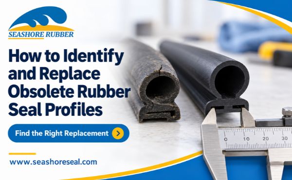
How to Identify and Replace Obsolete Rubber Seal Profiles
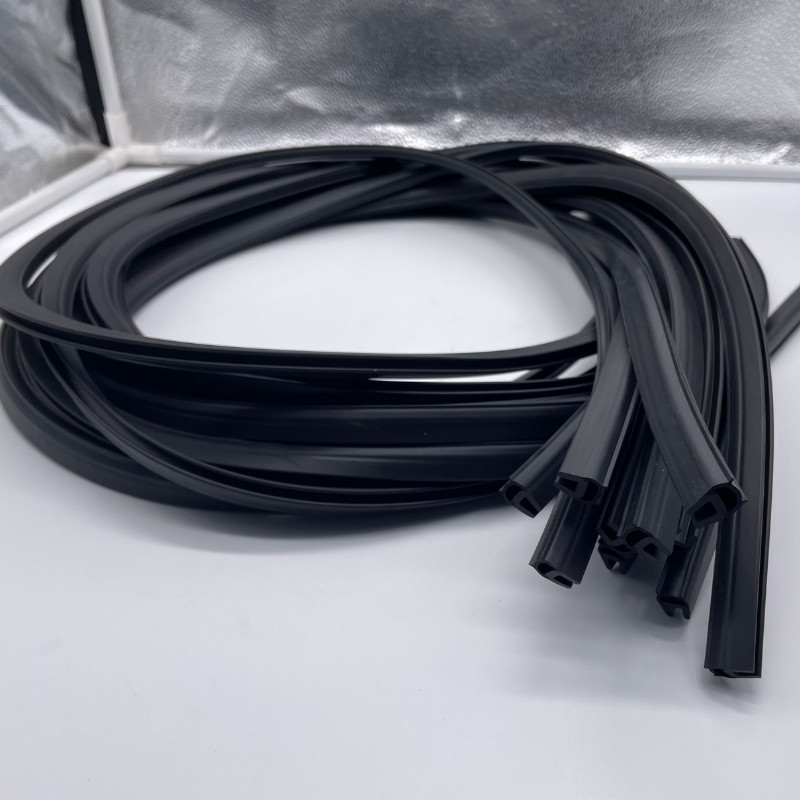
Identify obsolete rubber seal profiles by documenting their cross-section, mounting features, material requirements and installed sealing gap. Then compare available profiles or develop a custom replacement around those functional requirements. A similar-looking extrusion is only a candidate until it fits, stays retained and seals without unacceptable closing force.
This approach is useful when an original part number has disappeared, equipment is no longer supported or a seal supplier has discontinued its tooling. The goal is to recover the original sealing function, not simply copy the dimensions of a worn, flattened sample.
Establish the Seal’s Function and Original Installation
Before removal, photograph the seal in place and record its orientation. Show how the door, lid, panel or glass contacts it. Note whether the profile seals by bulb compression, lip deflection or another mechanism.
Identify the retention method. Adhesive-backed profiles, push-in stems, self-gripping edge carriers and locking glazing gaskets require different replacement checks. Adding adhesive to a poorly fitting mechanical profile does not necessarily reproduce its intended retention.
Search existing maintenance records, drawings and labels for an original part number. A discontinued code may have a documented successor, but equipment model information should be treated as a search aid rather than proof of fit.
Inspect the surrounding assembly as well. Bent panels, worn hinges, damaged channels or loose latches may explain a leak even when the seal is intact. Replacing the rubber alone will not reliably correct a mounting or alignment defect.
Record where failure occurs: straight lengths, corners, end joints or particular door positions. This information helps separate an unsuitable profile from a local installation problem and gives the replacement supplier a clearer application brief.
Capture a Usable Cross-Section and Mounting Dimensions
A straight-on photograph of the cut end is more useful than a side view. Where removal is permitted, take a clean sample from a relatively undamaged area and preserve its orientation. Keep a second sample if the profile changes through a molded corner or joint.
Include a scale in the same plane as the cross-section, and provide measured dimensions separately. Photographs taken at an angle can distort proportions and should not be the sole basis for tooling.
Measure the Retention Features
For push-in profiles, document stem width, barbs, groove opening and relevant groove depth. For edge-gripping seals, measure the actual panel or flange thickness and identify coating buildup. A nominal panel size may not represent the fitted edge.
For adhesive-backed sections, measure the flat mounting land and document available panel space. For glazing gaskets, glass thickness, panel thickness and locking-strip details can be essential. Overall width and height alone do not establish fit.
Measure the Sealing Features
Record bulb height, lip reach, cavity shape and visible wall thickness where practical. Show the compression direction and contact location on a simple drawing. Mark any dimensions that remain uncertain because the sample is damaged.
Do not squeeze soft sponge profiles with calipers and then record the compressed result as their free height. Use a method that avoids unintended deformation. A physical sample and mating-part dimensions can resolve uncertainties that photographs cannot.
Recover Functional Dimensions from the Assembly
An old seal may have compression set, stretching, shrinkage or surface damage. Its present dimensions are evidence of condition, not necessarily the original design. Compare several sample locations with the mating assembly before selecting a replacement.
Measure the closed gap at relevant positions, including corners and areas affected by panel alignment. Keep the closure in its normal operating condition. A gap measured with a latch released may differ from the gap the seal must actually accommodate.
For a simple bulb compressed between parallel surfaces, nominal compression can be estimated as:
Compression (%) = (free bulb height − installed gap) ÷ free bulb height × 100.
The dimensions must refer to the same mounting datum. This estimate does not directly describe a bending lip, complex hollow section or profile with a moving carrier. Use the proposed seal supplier’s guidance and confirm the result through an installed trial.
Do not apply one compression percentage to every rubber seal profile. Geometry, compound, cellular structure and closing-force limits affect the appropriate range. Excessive interference can make a door difficult to close, while inadequate contact may leave leakage paths.
Match Material Behavior Alongside Profile Shape
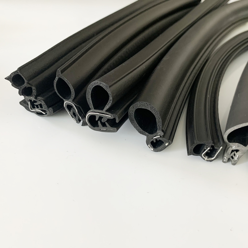
Determine whether the original seal is solid, sponge or a combination of materials. A hollow solid extrusion and a cellular profile can look similar from a distance yet respond differently during compression.
Document service temperature, weather exposure, cleaning chemicals and any oil contact. Select a replacement compound for those conditions rather than assuming that all black rubber has equivalent resistance. Appearance or touch alone cannot reliably identify the polymer.
Hardness may help specify solid rubber, but it does not fully describe the force required to close an assembled seal. For cellular materials, compression force-deflection information is more useful than relying only on a Shore hardness number. Profile geometry still affects the completed seal’s behavior.
Check coatings, flocking and reinforcement separately. A sliding contact surface may need a suitable low-friction treatment. An edge carrier may depend on internal reinforcement, while a co-extruded profile may combine a firm retention base with a compliant sealing portion.
If the original compound cannot be identified, define the replacement through known service requirements and appropriate material evaluation. Do not promise chemical or temperature equivalence based on a geometric match.
Compare Stock Profiles, Adaptations and Custom Reproduction
Choose the simplest replacement route that can demonstrate the required function. A catalog match can shorten development, but customization may be necessary when retention or contact geometry is unusual.
| Replacement route | Suitable situation | Evidence needed before approval |
|---|---|---|
| Documented successor part | Original supplier provides an updated reference | Fit and stated application compatibility |
| Existing standard profile | Mounting and sealing dimensions are compatible | Installed trial and material suitability |
| Modified standard profile | Secondary fabrication can meet the requirement | Joint, corner and dimensional validation |
| Custom reproduction | No existing section provides the required function | Approved drawing, compound and production sample |
For custom rubber extrusions, an old sample should support development rather than serve as the only specification. Define critical mounting dimensions, tolerances, material construction and finished lengths on an approved drawing.
Include secondary operations: joining, molded corners, holes, adhesive backing or formed rings. An extruded section matching the straight sample may still fail if its joints or corners are unsuitable.
For repeat orders, preserve the approved specification and physical reference. This reduces dependence on repeatedly identifying the same obsolete profile from photographs.
Validate and Install the Replacement Without Distortion
Test a representative replacement in the actual mounting system before ordering the complete quantity. Check retention, corner behavior, continuous contact and closing effort. A short straight sample may confirm local fit but cannot establish the performance of an entire perimeter.
Clean the mounting area using a procedure compatible with its coating and the proposed attachment system. Repair relevant assembly defects before installation. Avoid stretching the replacement to fit the perimeter unless the specific installation procedure requires it.
Use the approved corner and end-joint method, and observe any adhesive bond-development requirements. Do not use a universal extra-length allowance; cut-length instructions depend on the profile and assembly.
Verify the intended function after installation. Depending on the application, this may require a suitable water, air-leakage or operational test. Repeat opening and closing to check displacement and interference, and record the accepted replacement for future maintenance.
Conclusion
Replacing obsolete rubber seal profiles requires a functional specification built from the sample and the mating assembly. Document retention, gap, compression behavior and material exposure, then validate the proposed replacement across the complete installation. This establishes a repeatable maintenance solution even when the original part and supplier are no longer available.


Leave a Reply
Want to join the discussion?Feel free to contribute!